이번 과정은 STM32 보드와 추가로 제작된 확장보드 및 RC카 구동체를 이용해서 자동차를 제어하기 위한 간단한 프로그램을 만드는 과정의 세 번째로 확장보드의 모터 드라이버를 이용해 모터를 제어하는 과정입니다.
아래 과정은 이전 과정을 완료 후 진행하시길 추천드립니다.
모터를 제어하기 위해서는 아래 그림과 같이 12V 전원과 모터 구동체가 확장보드에 연결되어 있어야 합니다.

1. 통신규격 추가하기
- 기존에 정의한 통신 규격에 모터제어를 위한 명령을 추가합니다.
- 우선 아래 코드와 같이 bsp_uart.h 에 COMMAND 및 RESULT를 정의합니다. 0x03 CMD_MOTOR이 추가됐습니다.
/* BSP UART command */
#define CMD_LED		0x01
#define CMD_BUZZER	0x02
#define CMD_MOTOR	0x03

/* BSP UART error */
#define REQUEST		0x00
#define RES_OK 0x01- python의 Car_driver.py에도 아래와 같이 COMMAND 및 RESULT를 정의합니다.
# BSP UART command
CMD_LED = 0x01
CMD_BUZZER = 0x02
CMD_MOTOR = 0x03

# BSP UART error
REQUEST = 0x00
RES_OK = 0x01- 확장보드를 통해 모터를 제어를 위해서는 아래와 같이 STM32 보드에 보내면 됩니다.
◦ COMMAND: 0x03
◦ RESULT: 0x00
◦ DATA: [speed1 (2byte), speed2 (2byte), speed3 (2byte), speed4 (2byte) ]
2. STM32 - 메시지 수신 및 제어 기능 구현 (MOTOR)
- 'Timer' >> 'TIM3'에서 아래와 같이 설정합니다.
◦ Clock Source: Internal Clock
◦ Channel 1: PWM Generation CH1
◦ Channel 2: PWM Generation CH2
◦ Channel 3: PWM Generation CH3
◦ Channel 4: PWM Generation CH4
◦ Prescaler: 71
◦ Counter Period: 999
◦ Pulse: 0
◦ PC6: TM3_CH1
◦ PC7: TM3_CH2
◦ PC8: TM3_CH3
◦ PC9: TM3_CH4
- 'System Core' >> 'GPIO'에서 아래와 같이 설정합니다.
◦ PA11: GPIO_Output, DIR1
◦ PB0: GPIO_Output, DIR2
◦ PA8: GPIO_Output, DIR3
◦ PB1: GPIO_Output, DIR4
- 툴바의 'Device Configuration Tool Code Generation' 버튼을 눌러서 코드를 생성합니다.
- 아래와 같이 'bsp_uart.h' 파일을 수정합니다.
#ifndef BSP_UART_H_
#define BSP_UART_H_

/* BSP UART command */
#define CMD_LED		0x01
#define CMD_BUZZER	0x02
#define CMD_MOTOR	0x03

/* BSP UART error */
#define REQUEST		0x00
#define RES_OK		0x01

/* BSP UART function */
void USART2_Init(void);

#endif /* BSP_UART_H_ */- 다음은 아래와 같이 'bsp_uart.c' 파일을 수정합니다.
#include <string.h>
#include "main.h"
#include "bsp_uart.h"


extern UART_HandleTypeDef huart2;
uint8_t rx_flag;
uint8_t rx_data[256];
uint8_t rx_csum;
uint8_t tx_data[256];
uint8_t tx_csum;

extern TIM_HandleTypeDef htim3;


void USART2_Init(void)
{
	HAL_UART_Receive_IT(&huart2, &rx_flag, 1);
}

int Check_RxCheckSum() {
	int len = rx_data[1] + 2;
	int sum = 0;
	for(int i = 0; i < len; i++) {
		sum += rx_data[i];
	}
	sum &= 0xFF;
	return rx_csum == sum;
}

void Make_TxCheckSum() {
	int len = tx_data[1] + 2;
	int sum = 0;
	for(int i = 0; i < len; i++) {
		sum += tx_data[i];
	}
	tx_csum = sum & 0xFF;
}

void Send_Data() {
	Make_TxCheckSum();
	HAL_UART_Transmit(&huart2, tx_data, tx_data[1] + 2, 10);
	HAL_UART_Transmit(&huart2, &tx_csum, 1, 10);
}

void Set_Led() {
	if (rx_data[3] == CMD_LED) {
		HAL_GPIO_WritePin(LED2_GPIO_Port, LED2_Pin, rx_data[5]);

		// response
		memset(tx_data, 0x00, sizeof(tx_data));
		memcpy(tx_data, rx_data, rx_data[1] + 2);
		tx_data[4] = RES_OK; // result
		Send_Data(); // send result
	}
}

void Set_Buzzer() {
	if (rx_data[3] == CMD_BUZZER) {
		HAL_GPIO_WritePin(BUZZER_GPIO_Port, BUZZER_Pin, rx_data[5]);

		// response
		memset(tx_data, 0x00, sizeof(tx_data));
		memcpy(tx_data, rx_data, rx_data[1] + 2);
		tx_data[4] = RES_OK; // result
		Send_Data(); // send result
	}
}

void Set_Motor() {
	if (rx_data[3] == CMD_MOTOR) {
		short speed1 = (rx_data[5] << 8) | rx_data[6];
		short speed2 = (rx_data[7] << 8) | rx_data[8];
		short speed3 = (rx_data[9] << 8) | rx_data[10];
		short speed4 = (rx_data[11] << 8) | rx_data[12];

		// motor 1
		int dir1 = 1;
		if (speed1 < 0) {
			speed1 = -speed1;
			dir1 = 0;
		}
		if (speed1 < 0) speed1 = 0;
		else if (speed1 > 950) speed1 = 950;
		TIM3->CCR1 = speed1;
		HAL_GPIO_WritePin(DIR1_GPIO_Port, DIR1_Pin, dir1);

		// motor 2
		int dir2 = 1;
		if (speed2 < 0) {
			speed2 = -speed2;
			dir2 = 0;
		}
		if (speed2 < 0) speed2 = 0;
		else if (speed2 > 950) speed2 = 950;
		TIM3->CCR2 = speed2;
		HAL_GPIO_WritePin(DIR2_GPIO_Port, DIR2_Pin, dir2);

		// motor 3
		int dir3 = 1;
		if (speed3 < 0) {
			speed3 = -speed3;
			dir3 = 0;
		}
		if (speed3 < 0) speed3 = 0;
		else if (speed3 > 950) speed3 = 950;
		TIM3->CCR3 = speed3;
		HAL_GPIO_WritePin(DIR3_GPIO_Port, DIR3_Pin, dir3);

		// motor 4
		int dir4 = 1;
		if (speed4 < 0) {
			speed4 = -speed4;
			dir4 = 0;
		}
		if (speed4 < 0) speed4 = 0;
		else if (speed4 > 950) speed4 = 950;
		TIM3->CCR4 = speed4;
		HAL_GPIO_WritePin(DIR4_GPIO_Port, DIR4_Pin, dir4);

		// response
		memset(tx_data, 0x00, sizeof(tx_data));
		memcpy(tx_data, rx_data, rx_data[1] + 2);
		tx_data[4] = RES_OK; // result
		Send_Data(); // send result
	}
}

void HAL_UART_RxCpltCallback(UART_HandleTypeDef *huart)
{
	if (huart->Instance == USART2) {
		if (rx_flag == 0xFF) {
			memset(rx_data, 0x00, sizeof(rx_data));
			rx_data[0] = rx_flag;
			HAL_StatusTypeDef uartState = HAL_UART_Receive(&huart2, &rx_data[1], 1, 10); // recv len
			if (uartState == HAL_OK) {
				uartState = HAL_UART_Receive(&huart2, &rx_data[2], rx_data[1], 10); // recv data
			}
			if (uartState == HAL_OK) {
				uartState = HAL_UART_Receive(&huart2, &rx_csum, 1, 10); // recv crc
			}

			if (uartState == HAL_OK && Check_RxCheckSum() > 0) {
				switch (rx_data[3]) {
					case CMD_LED:
						Set_Led();
						break;
					case CMD_BUZZER:
						Set_Buzzer();
						break;
					case CMD_MOTOR:
						Set_Motor();
						break;
				}
			}
		}
		HAL_UART_Receive_IT(&huart2, &rx_flag, 1);
	}
}- 다음은 아래 그림과 같이 툴바의 'Build Debug' 버튼을 눌러 컴파일을 진행합니다.
- 다음은 아래 그림과 같이 툴바의 'Debug' 버튼을 눌러서 프로그램을 보드에 다운로드합니다.
3. Python - STM32 보드 제어기능 구현 (MOTOR)
- 아래와 같이 보드를 제어하기 위한 'Car_driver.py' 코드를 작성합니다.
import itertools
import threading

import serial

# BSP UART command
CMD_LED = 0x01
CMD_BUZZER = 0x02
CMD_MOTOR = 0x03

# BSP UART error
REQUEST = 0x00
RES_OK = 0x01


class CarDriver:
    def __init__(self, baudrate=115200, port="COM1"):
        # unique seq counter
        self.seq = itertools.count()
        # serial communication driver
        self.ser = serial.Serial()
        self.ser.baudrate = baudrate
        self.ser.port = port
        self.ser.open()
        # serial recive thread run
        self.run_receive_thread()

    def run_receive_thread(self):
        task_receive = threading.Thread(target=self.__recv_data, name="serial_recv_task")
        task_receive.setDaemon(True)
        task_receive.start()

    def __recv_data(self):
        while True:
            data = bytearray(self.ser.read())[0]
            print(data)

    def set_led(self, state):
        self.__send_data(CMD_LED, [1 if state else 0])

    def set_buzzer(self, state):
        self.__send_data(CMD_BUZZER, [1 if state else 0])

    def set_motor(self, speed1, speed2, speed3, speed4):
        data = []
        data.extend(speed1.to_bytes(2, "big", signed=True))
        data.extend(speed2.to_bytes(2, "big", signed=True))
        data.extend(speed3.to_bytes(2, "big", signed=True))
        data.extend(speed4.to_bytes(2, "big", signed=True))
        self.__send_data(CMD_MOTOR, data)

    def __send_data(self, command, data):
        seq = next(self.seq) % 0xFE + 1
        cmd = [0xFF, 0, seq, command, REQUEST]
        cmd.extend(data)
        cmd[1] = len(cmd) - 2
        checksum = sum(cmd) & 0xFF
        cmd.append(checksum)
        print(cmd)
self.ser.write(cmd)- 다음은 보드를 제어하기 위한 'Car_driver_test.ipynb' 파일의 내용을 아래와 같이 바꿉니다.
from ipywidgets import interact
import ipywidgets as widgets
from Car_driver import CarDriver
driver = CarDriver(baudrate=115200, port="COM5")
driver.set_led(True)
driver.set_led(False)
driver.set_buzzer(True)
driver.set_buzzer(False)
driver.set_motor(0, 0, 0, 0)
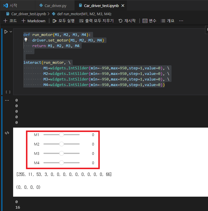
def run_motor(M1, M2, M3, M4):
driver.set_motor(M1, M2, M3, M4)
return M1, M2, M3, M4
interact(run_motor, \
M1=widgets.IntSlider(min=-950,max=950,step=1,value=0), \
M2=widgets.IntSlider(min=-950,max=950,step=1,value=0), \
M3=widgets.IntSlider(min=-950,max=950,step=1,value=0), \
M4=widgets.IntSlider(min=-950,max=950,step=1,value=0))- 아래 그림과 같은 실행화면에서 M1, M2, M3, M4 슬라이드를 조절하면 모터를 제어할 수 있습니다.
'로봇 > STM32' 카테고리의 다른 글
| STM32 자동차 제어하기(2) - LED / BUZZER 제어하기 (0) | 2023.03.19 |
|---|---|
| STM32 자동차 제어하기(1) - 기본환경 설정 (0) | 2023.03.19 |
| STM32 UART로 보드 제어하기 (1) | 2023.03.01 |
| STM32 Button을 누르면 UART로 메시지 출력하기 (2) | 2023.02.28 |
| STM32 Button Interrupt를 이용한 LED 제어 (0) | 2023.02.28 |