로봇/ESP32
ESP32를 이용한 WiFi-Serial Bridge 만들기
with-RL
2023. 7. 11. 09:29
이 포스트는 ESP32의 WiFi를 통해 수신한 데이터를 serial을 이용해 출력하는 기능을 만들어 보는 과정에 대한 설명입니다.
이 과정은 다음 환경에서 구성했습니다.
- Windows 11
- Arduino IDE 1.8.19
- ESP32-CAM
- ESP32-CAM-MB
- Visual Studio Code
- Python-3.7

1. WiFi-Serial Bridge 설명
- ESP32에 포함된 WiFi를 이용해서 원격으로 데이터를 주고 받을 수 있습니다. WiFi-Serial Bridge는 ESP32 WiFi를 통해서 수신한 명령을 Serial 통신을 이용해 다른 MCU 장비에 전달하고 그 결과를 다시 WiFi를 통해 전달하는 기능입니다.

- WiFi to Serial Bridge는 다음과 같이 동작합니다.
◦ PC에서 WiFi를 통해 ESP32에 메시지를 전달합니다.
◦ ESP32는 수신한 메시지를 Serial을 통해 PC에 전달합니다. - Serial to WiFi Bridge는 다음과 같이 동작합니다.
◦ PC에서 Serial을 통해 ESP32에 메시지를 전달합니다.
◦ ESP32는 수신한 메시지를 WiFi을 통해 PC에 전달합니다.
2. PC에 ESP32 연결하기
- ESP32 보드에 USB-5핀을 연결하고 USB-A를 노트북에 연결합니다.
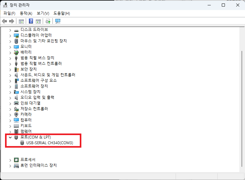
- Windows의 장치관리자를 실행합니다.

- ‘장치 관리자’에서 ‘포트(COM & LPT)’의 정보를 확인하면 연결된 COM 포트를 확인할 수 있습니다. 제 경우는 ‘COM3’으로 연결된 것을 확인할 수 있습니다.
3. ESP32 코드 (Arduino IDE)
- ‘Arduino IDE’를 실행하고 메뉴에서 ‘파일’ >> ‘새 파일’을 선택합니다.

- 새로운 창 메뉴에서 ‘툴’ >> ‘보드’ >> ‘ESP32 Arduino’ >> ‘ESP32 Wrover Module’을 선택합니다.

- 메뉴 툴에서 나머지 옵션을 아래와 같이 설정합니다.
◦ Upload Speed: 115200
◦ Flash Frequency: 80MHz
◦ Flash Mode: QIO
◦ Partition Scheme: Default 4MB with spiffs
◦ Core Debug Level: None
◦ Erase All Flash Before Sketch Upload: Disabled
◦ 포트: COM3 (본인 PC에 연결된 포트를 선택하세요.)

- ESP32에서 나오는 출력을 확인하기 위해 메뉴에서 ‘툴’ >> ‘시리얼 모니터’를 실행합니다.

- 아래와 같은 ‘시리얼 모니터’ 창을 확인할 수 있습니다.

- 이제 코드를 아래와 같이 수정합니다. 아래 코드에서 다음 두 부분은 본인의 환경에 맞게 수정하시면 됩니다.
◦ ssid: 접속하고자 하는 WiFi SSID
◦ password: 접속하고자 하는 WiFi 비밀번호
#include <WiFi.h>
#include <WiFiClient.h>

const char* ssid = "SSID of WiFi";
const char* password = "password of WiFi";

WiFiServer tcpServer(5000);
WiFiClient tcpCleint;

uint8_t rx_buf[1024];
uint16_t rx_len = 0;
uint8_t tx_buf[1024];
uint16_t tx_len = 0;

void setup() {
  Serial.begin(115200);
  Serial.setDebugOutput(true);
  Serial.println();

  WiFi.begin(ssid, password);
  while (WiFi.status() != WL_CONNECTED) {
    delay(500);
    Serial.print(".");
  }
  Serial.println("");
  Serial.println("WiFi connected.");
  Serial.print("IP address: ");
  Serial.println(WiFi.localIP());

  tcpServer.begin();
  tcpServer.setNoDelay(true);
}

void loop() {
  if (tcpServer.hasClient()) {
    if (!tcpCleint || !tcpCleint.connected()) {
      tcpCleint = tcpServer.available();
      Serial.println("accept new Connection ...");
    } else {
      WiFiClient temp = tcpServer.available();
      temp.stop();
      Serial.println("reject new Connection ...");
    }
  }

  if (!tcpCleint || !tcpCleint.connected()) {
    delay(100);
    return;
  }

  while(tcpCleint.connected()) {
    if (tcpCleint.available()) {
      while (tcpCleint.available()) {
        rx_buf[rx_len] = tcpCleint.read();
        rx_len++;
      }
      Serial.write(rx_buf, rx_len);
      rx_len = 0;
    }
    if (Serial.available()) {
      while (Serial.available()) {
        tx_buf[tx_len] = Serial.read();
        tx_len++;
      }
      tcpCleint.write(tx_buf, tx_len);
      tx_len = 0;
    }
    delay(1);
  }
}
- 이미지 다운로드를 위해서 ESP32를 아래 절차대로 다운로드 모드로 전환합니다. 아래 절차는 ESP32-CAM과 ESP32-CAM-MB가 연결된 상태에서 실행합니다.
◦ ESP32-CAM-MB의 ‘Download Button’을 누르고 있습니다.
◦ ‘Download Button’을 누른 상태에서 ESP32-CAM-MB의 ‘Reset Button’을 눌렀다 뗍니다.
◦ ESP32-CAM-MB의 ‘Download Button’을 뗍니다.

- 아래와 같은 ‘시리얼 모니터’ 창에서 ‘waiting for download’ 메시지를 확인할 수 있습니다.

- Arduino IDE의 ‘업로드’ 버튼을 눌러서 프로그램을 컴파일하고 업로드합니다. 소스코드가 컴파일되고 업로드됩니다.

- ‘시리얼 모니터’ 창에 ‘WiFi Connected’ 및 ‘IP address’가 출력 되면 정상 실행이 된 겁니다. 아래 결과에서 ‘192.168.45.186’은 ESP32의 WiFi IP address입니다.

3. Python 코드 (VSCode)
- Python을 이용해서 WiFi를 이용해 ESP32에 메시지를 전달하고 수신하는 기능을 구현하는 과정입니다.
- 초기 프로젝트 설정은 ‘VSCode 설치 및 python 개발 환경 구축‘을 참고하세요.
- VSCode에서 ‘ESP32_WiFi_test.ipynb’ 파일을 생성하고 아래와 같이 편집합니다. 아래 코드 중 host는 ESP32의 IP address를 입력하면 됩니다.
import socket
import time

host = '192.168.45.186'
port = 5000

client = socket.socket(socket.AF_INET, socket.SOCK_STREAM)
client.connect((host, port))
- 이제 이 코드를 모두 실행합니다.
4. WiFi to Serial Bridge 시험
- VSCode에서 ‘ESP32_WiFi_test.ipynb’ 파일에 아래 코드를 추가하고 실행합니다.
client.send(f'Send from WiFi to serial {time.time()}\n'.encode())
- ESP32의 ‘시리얼 모니터’ 창에 Python에서 WiFi를 통해서 보낸 메시지가 출력된 것을 확인할 수 있습니다.

- Python에서 방금 추가한 ‘client.send()’ 코드를 여러 번 실행하면 ‘시리얼 모니터’에 그 값이 출력되는 것을 확인할 수 있습니다.

5. Serial to WiFi Bridge 시험
- VSCode에서 ‘ESP32_WiFi_test.ipynb’ 파일에 아래 코드를 추가하고 실행합니다.
while True:
    data = client.recv(1024)
print(data)- ESP32의 ‘시리얼 모니터’ 창에서 적당한 메시지를 입력하고 우측 상단의 ‘전송’ 버튼을 누릅니다.

- VSCode에서 ‘ESP32_WiFi_test.ipynb’ 실행 결과에 ESP32 ‘시리얼 모니터’ 창에서 입력한 메시지가 출력되는 것을 확인할 수 있습니다.

- 추가로 ESP32의 ‘시리얼 모니터’ 창에서 적당한 메시지를 여러 입력 및 전송을 합니다. 그 값이 VSCode에서 ‘ESP32_WiFi_test.ipynb’ 실행 결과에 출력되는 것을 확인할 수 있습니다.
